
Tubes and Connectors in a Modular Honeycomb System
Published 2026-09-19
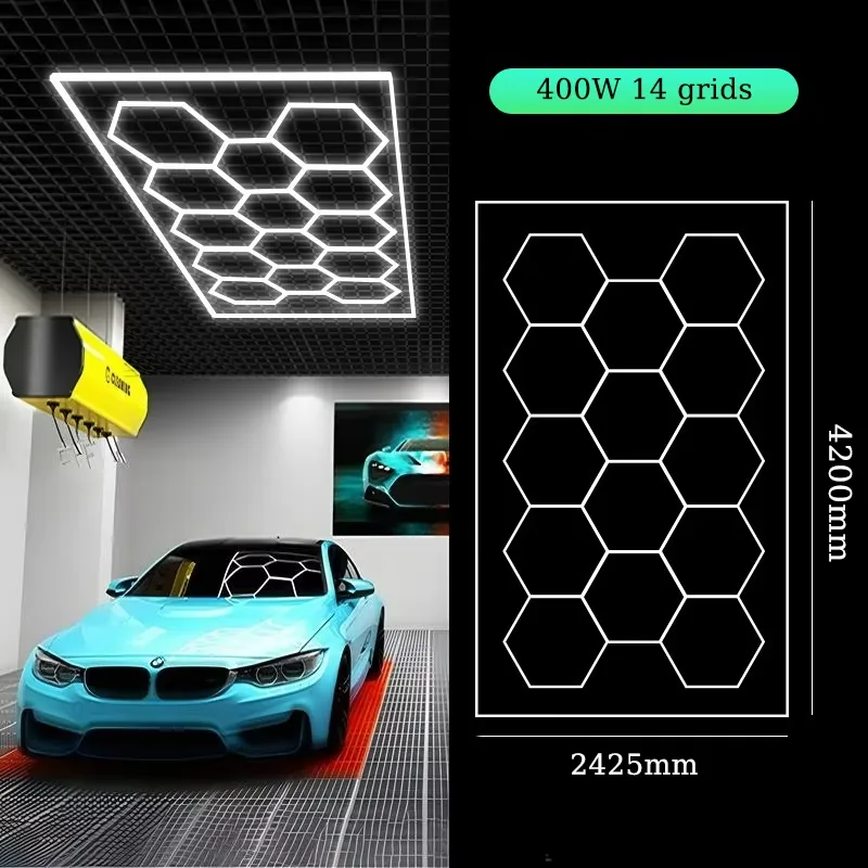
A honeycomb ceiling is assembled, not manufactured as one piece. The visible shape comes from straight tubes joined by connectors, which is the reason the same stock can produce a compact 1-grid feature and a ceiling-wide 14-grid layout. That makes the component range, rather than the finished appearance, the thing that decides what a layout can actually do.
Tube lengths in the range
Tubes are supplied in defined lengths. Everything in a layout is built from these, so the tube list is effectively the vocabulary the layout is written in.
| Tube type | Available lengths |
|---|---|
| PC tubes | 440 / 570 / 1175 mm |
| Aluminium tubes | 440 / 1175 mm |
| RGB tubes | 410 / 1210 mm |
Two shell materials are available. PC tubes are the lighter option and suit the standard white-light systems. Aluminium tubes act as a continuous heat path along the fixture, which is why they appear in the higher-output configurations. RGB tubes come in their own lengths because the colour system uses different internal wiring.
Connectors and what each one does
Connectors join tubes and set the direction of the layout. The range covers V, I, L, Y, T, Cross, V60, E60, X and Snow types. In practice they fall into four jobs:
- Straight runs: I connectors continue a line without changing direction.
- Direction changes: L and V connectors turn a run, including the V60 used where the turn angle has to match a specific cell geometry.
- Junctions: T, Y and Cross connectors branch one run into two or more, which is how a grid widens without starting a separate system.
- Cell closure: X and Snow connectors close the hexagonal geometry where several runs meet at a point.
Because the shape is defined by these joints, a layout that looks simple on a photograph can require an unusual connector count. That is why we ask for the ceiling dimension rather than a picture to copy: two visually similar ceilings can need different connector lists if the available width falls on opposite sides of a tube length.
What the component approach means for a distributor
The practical benefit is replacement and growth. If a tube is damaged on site, the tube is changed and the rest of the layout stays untouched, which matters in a working wash bay where removing a whole ceiling system is not an option. The same logic covers expansion: a customer who later wants to extend the grid adds tubes and connectors, rather than replacing the installation.
For distributors this changes what should be held in stock. A small quantity of spare tubes and connectors, matched to the layouts actually sold in that market, covers most site problems without tying up capital in complete systems. The exact spare list should follow the confirmed layout, so the installer knows which parts belong to that project.
Matching tubes to the electrical family
Tube choice and electrical system are linked, because the three product families do not share the same supply.
| Family | Supply | LED |
|---|---|---|
| Single colour | AC85-265V | SMD2835, 6500 K, CRI 80 |
| 3 Colors Change | AC85-265V | SMD2835, 3000 / 4000 / 6500 K |
| Low-voltage RGB (directional) | DC24V | SMD2835 |
| Low-voltage RGB (non-directional) | DC5V | SMD5050 |
The AC families use the same wide input, so a white-light and a 3 Colors Change installation can coexist on one site supply. The RGB kits are deliberately low voltage and need their power supplies and remotes specified with the layout, which is why power-supply quantity is quoted per configuration rather than as a single line item.
Installation notes that prevent most callbacks
Set the pattern out on the floor before anyone works at ceiling height. Confirm the outside dimension, tube direction and connector positions against the approved drawing, and check the ceiling for beams, ducting or door tracks that will force the grid to move. Finding that conflict while the parts are on the floor costs minutes; finding it after one side is mounted costs a day.
Do not force a connector. If a joint does not line up easily, the tube orientation or the connector type is wrong, and forcing it hides an alignment error that will continue through the rest of the grid. Final electrical connection and testing should be carried out by a qualified electrician against the requirements that apply at the installation site.
Can a single tube be replaced without dismantling the layout?
Yes. Tubes and connectors are separate parts, so a damaged tube can be replaced on its own. The replacement must match the tube type and length, so keep the confirmed parts list for the project.
Can I mix PC and aluminium tubes in one layout?
They are not interchangeable within a run because the available lengths differ and the two materials behave differently thermally. Mixing belongs in the specification stage, not on site, so confirm the tube type before the order is placed.
Do I need a different connector set for a framed layout?
Framed and special-shape designs add perimeter structure around the cells, so the connector list is confirmed against the drawing rather than taken from a standard open-grid kit.
How many spare tubes should a distributor hold?
It depends on the layouts sold in that market rather than on a fixed ratio. The spare list should be built from the layouts actually delivered, so the parts on the shelf match the installations in the field.
If you need the component list for a specific ceiling, send the dimensions and we will confirm the tube and connector schedule alongside the layout.